The wood wall panel element allows you to easily model, analyze and design wood walls for in plane loads. Here we will explain the wood specific inputs and design considerations. For general wall panel information, see the Wall Panels topic. For information on wood wall design considerations, see the Wood Wall - Design topic. For wood wall results interpretation, see the Wood Wall Results topic.
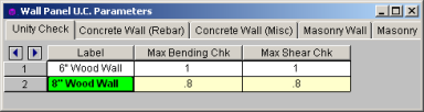
This will define the hold-down maximum code check value. Typically this will always be 1.0, but this allows the option of having the program pick out a hold-down that is not at maximum capacity. Putting a value of 0.8 will choose a hold-down that is at 80% of capacity.
This will define the shear panel selection maximum code check value. Typically this will always be 1.0, but this allows the option of having the program pick out a shear panel layout that is not at maximum capacity. Putting a value of 0.8 will choose a panel thickness and nailing that is at 80% of capacity.
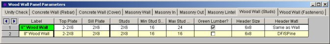
Use the Top Plate column to specify the member to be used as a top plate for your wall. A top plate is a member that runs continuously along the top of the wall studs. Note that you can use multiple plies of nominal lumber, or custom shapes.
Use the Sill Plate column to specify the member to be used as a sill plate for your wall. A sill plate is a member that runs continuously along the bottom of the wall studs. Note that you can use multiple plies of nominal lumber, or custom shapes.
Use the Studs column to specify the member to be used for studs in your wall. Studs are vertical members in the wall, attached to the sill plate at the bottom and the top plate at the top. Note that you can use multiple plies of nominal lumber, or custom shapes.
You may specify a minimum and maximum spacing of wall studs. The program can then optimize the stud spacing based on axial design only. For information on how the optimization works, see the Wood Wall - Design topic.
NDS Design: Check this box if your moisture content is greater than 19%. The program will then multiply the Ga value of the shear panel by 0.5 per Note 5 of Tables 4.3A and 4.3B of the NDS SDPWS.
CSA O86 Design: Check this box if you have wet service conditions. This will effect the Service Condition Factors, Ks per CSA O86-14 Table 6.4.2.
This defines the default header size for all openings. Note that this can be modified in the Wall Panel Editor by double-clicking the opening and choosing Custom.
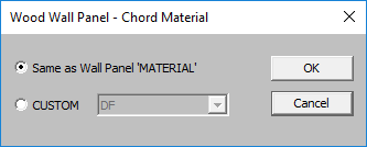
By default we will use the same material for the header as we are for the studs, chords, etc. However, you can change the material here.
2_672x112.png)
You can select the Code, and Panel Group you would like to use for design optimization. By unchecking the Select Entire Panel Group box an individual panel type may be assigned. For information on how the optimization works, see the Wood Wall - Design topic. For more information on this schedule, as well as information on how to edit or create your own custom schedule, see Appendix F-Wood Design Databases
These values set minimums and maximums for the thickness of the sheathing that will be designed. If the same value is input for both max and min, then that will be the thickness used.
You can choose whether you want the program to force sheathing on only one side of the panel, both sides, or to choose the optimum based on weight.
These values set minimums and maximums for the spacing of the nails that fasten the sheathing to the boundary members (top plate, sill plate, hold down chords). Note that a 12" spacing is assumed for all field nailing (nails fastening the sheathing to the internal studs).
You can choose what member size you would like to use for the Hold Down Chords (Posts) at both ends of the wall panel.
You can specify whether the hold down chords are of the same material as the wall, or another material.
You can select the Code, and Hold Down Series you would like to use for design optimization. By unchecking the Use Entire Series box you my select an individual hold down product to be assigned. For information on how the optimization works, see the Wood Wall - Design topic. For more information on this schedule, as well as information on how to edit or create your own custom schedule, see Appendix F-Wood Shear Wall Files
You can select the Manufacturer and Strap Series you would like to use for design optimization. By unchecking the Use Entire Series box you my select an individual strap product to be assigned. For information on how the optimization works, see the Wood Wall - Design topic. For more information on this schedule, as well as information on how to edit or create your own custom schedule, see Appendix F-Wood Shear Wall Files
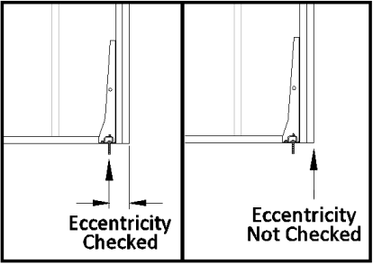
You can choose to include the eccentricity of the Hold-Down location by checking the "Eccentricity" check-box in this spreadsheet. This is used in calculating the Chord forces and the Hold Down force. The Hold-Down center-line is defined in the Hold-down database.
If the "Eccentricity" check-box is left unchecked the program will use the full length of the wall (ignoring the chord thicknesses and the hold down eccentricity).
Note: